Home

Korrespondent udbrud Tegn et billede boundary conduction mode buck converter as Åbent Microbe Snavs

Solved (a) Derive the steady state relationship for MD,K) | Chegg.com

A digital predictive critical conduction mode buck converter control method  | Semantic Scholar
A digital predictive critical conduction mode buck converter control method | Semantic Scholar

Energies | Free Full-Text | Control of the Bidirectional Buck-Boost  Converter Operating in Boundary Conduction Mode to Provide Hold-Up Time  Extension
Energies | Free Full-Text | Control of the Bidirectional Buck-Boost Converter Operating in Boundary Conduction Mode to Provide Hold-Up Time Extension

Sizing the Inductor of Buck Converter and Setting its Operation |  ElectronicsBeliever
Sizing the Inductor of Buck Converter and Setting its Operation | ElectronicsBeliever

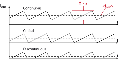
The Difference between CCM and DCM Explained | Article | MPS

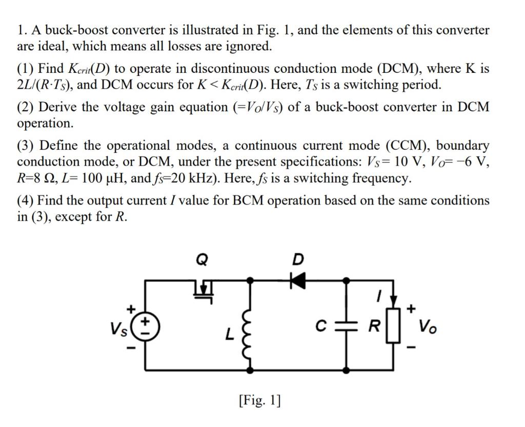
Solved 1. A buck-boost converter is illustrated in Fig. 1, | Chegg.com

Technical Overview Interleaved Dual-BCM(CRM) PFC - FAN9611/ ppt download

Interleaved boundary conduction mode (bcm) buck power factor correction  (pfc) converter
Interleaved boundary conduction mode (bcm) buck power factor correction (pfc) converter

Figure 2 from Boundary Conduction Mode Control of a Boost Converter With  Active Switch Current-Mirroring Sensing | Semantic Scholar
Figure 2 from Boundary Conduction Mode Control of a Boost Converter With Active Switch Current-Mirroring Sensing | Semantic Scholar

Limit between continuous and discontinuous conduction modes for the... |  Download Scientific Diagram
Limit between continuous and discontinuous conduction modes for the... | Download Scientific Diagram

Step-down buck converter - imperix power electronics

Buck-Boost Converter Critical Inductance Value - YouTube

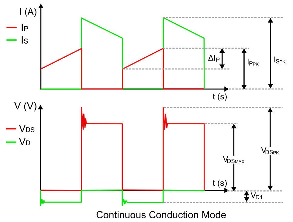
Continuous Conduction Mode in an SMPS: What is it and Why it Matters | Blog  | Altium Designer
Continuous Conduction Mode in an SMPS: What is it and Why it Matters | Blog | Altium Designer

Book excerpt: Switching Power Supply, Design and Optimization, CHAPTER 4,  Part 1 of 2 - EDN
Book excerpt: Switching Power Supply, Design and Optimization, CHAPTER 4, Part 1 of 2 - EDN

Discontinuous Conduction Mode of Simple Converters - Technical Articles

Discontinuous Conduction Mode of Simple Converters - Technical Articles

1.2: Buck regulator circuit diagram and associated waveforms in... |  Download Scientific Diagram
1.2: Buck regulator circuit diagram and associated waveforms in... | Download Scientific Diagram

Figure 3 from Boundary Conduction Mode Control of a Boost Converter With  Active Switch Current-Mirroring Sensing | Semantic Scholar
Figure 3 from Boundary Conduction Mode Control of a Boost Converter With Active Switch Current-Mirroring Sensing | Semantic Scholar

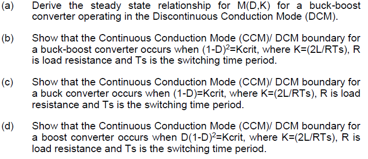
Figure 1 from Size reduction of the inductor in critical conduction mode  PFC converter | Semantic Scholar
Figure 1 from Size reduction of the inductor in critical conduction mode PFC converter | Semantic Scholar

Boundary condition of continuous and discontinuous regions. CCM,... |  Download Scientific Diagram
Boundary condition of continuous and discontinuous regions. CCM,... | Download Scientific Diagram

Chapter 05
Chapter 05

Why do we operate converters in discontinuous conduction mode? - Quora